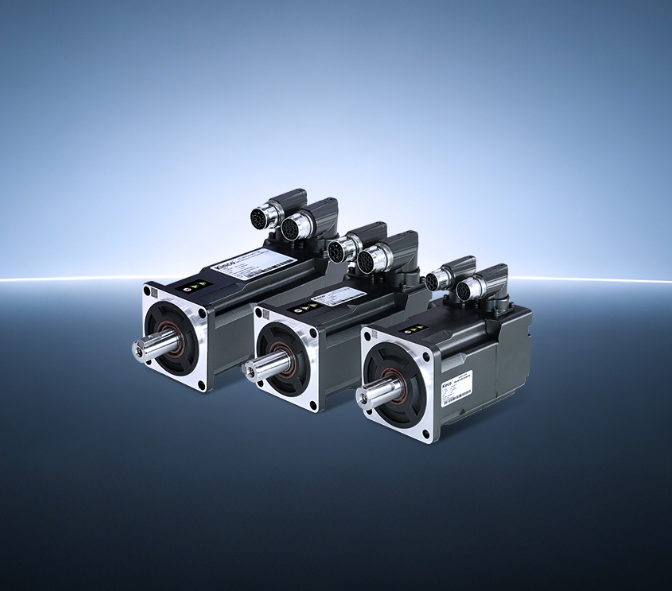
Vibration in a high-speed AC servo motor system is rarely a single-cause problem. It announces itself through audible noise, visible oscillation, or positioning errors that degrade product quality. The underlying sources can be mechanical, electrical, or control-related—and they often interact.
Addressing vibration effectively means working through the system methodically, from the mechanical coupling to the drive parameters. Here is a practical framework for reducing vibration in high speed servo motor applications where speed and precision both matter.
Where High-Speed Vibration Originates
At high rotational speeds, small imperfections become significant disturbances. The most common source is mechanical resonance, where the natural frequency of the load or coupling aligns with excitation frequencies from the motor.
Couplings, gearboxes, belts, and other elastic transmission elements introduce resonant modes that reduce system stability and can cause persistent oscillation at the motor shaft.
Torque ripple and cogging torque are motor-internal sources. Even well-designed motors exhibit some variation in torque output as the rotor rotates. At high speeds, these variations translate into high-frequency excitation that can couple with mechanical resonances. A well-designed motor minimizes cogging torque at the structural level, reducing the vibration energy that reaches the rest of the system.
Mechanical Design as the First Line of Defense
Vibration suppression begins before the motor is ever powered on. The mechanical interface between the motor and the load determines how much excitation reaches the driven structure. A rigid coupling transmits disturbances directly, while an elastic coupling can introduce additional resonant modes.
Mounting stiffness is equally critical. A motor mounted on a flexible bracket will oscillate at frequencies far lower than the control loop can compensate for. Increasing structural rigidity—through thicker mounting plates, additional support points, or stiffer materials—raises the natural frequency of the mechanical system, often moving it outside the operating range where excitation occurs.
For systems with significant load inertia, the inertia ratio between motor and load matters. High inertia mismatches make the control loop work harder to maintain stability, increasing the likelihood of oscillation. Reducing the ratio through gearing or load redesign can dramatically improve vibration behavior without changing any electrical parameters.
Drive-Based Suppression: Filters and Algorithms
When mechanical improvements reach their practical limit, the drive electronics take over. Modern servo drives incorporate multiple layers of vibration suppression that operate in real time.
Notch filters are the most widely used tool for mechanical resonance suppression. A notch filter attenuates gain at a specific frequency, effectively notching out the resonant peak without affecting performance at other frequencies. Advanced drives implement adaptive notch filters that track the resonance frequency as it shifts with temperature, wear, or load changes. This is particularly valuable in high-speed applications where operating conditions vary continuously.
S-curve acceleration profiles reduce vibration by shaping the motion command itself. Unlike trapezoidal profiles that apply abrupt changes in acceleration, S-curves limit jerk—the rate of change of acceleration. This reduces high-frequency harmonics in the excitation spectrum, allowing faster settling times without mechanical redesign. The motion becomes smoother because less vibrational energy is injected into the connecting mechanisms and the load.
Low-pass filters on the speed feedback and torque command smooth out high-frequency noise that would otherwise excite resonances. These filters trade off some responsiveness for reduced vibration, and the optimal setting depends on the mechanical time constant of the system.
Kinco‘s fifth-generation servo drives combine adaptive notch filters with S-curve acceleration profiles in an auto-tuning architecture that effectively dampens mechanical resonance and operational noise. The adaptive nature of the suppression means the system continues to perform as mechanical characteristics change over time.
The Tuning Sequence That Matters
The order of adjustments affects the outcome. Starting with the wrong parameter can make vibration worse before it gets better. A disciplined sequence produces faster results with less frustration.
Begin with auto-tuning if the drive supports it. Auto-tuning routines measure the mechanical system’s response and set initial gains and filters automatically. This provides a baseline that is usually stable, even if not optimal. Many systems never need further adjustment.
If vibration persists after auto-tuning, identify when it occurs. Does the motor oscillate at standstill? That points to gain settings that are too high for the mechanical system, requiring a reduction in speed loop proportional gain or an increase in the speed feedback filter. Does the vibration occur only during acceleration or deceleration? That points to the motion profile, where S-curve shaping or jerk limiting is the appropriate intervention.
For resonance at a specific speed, use a notch filter. Modern drives allow manual configuration of notch filter frequency and depth. If the resonance frequency shifts during operation, an adaptive notch filter is the better choice.
For residual vibration after positioning, input shaping or vibration suppression filters that target the settling phase are effective. These filters modify the command signal to reduce residual oscillation during the settling phase.
The goal is not zero vibration—that is rarely achievable in high-speed mechanical systems. The goal is vibration that stays within acceptable limits for the application’s precision and noise requirements.
A systematic approach, moving from mechanical design to drive filters to tuning adjustments, consistently produces better results than trial-and-error adjustments of individual parameters.
